Laboratory Water Purification Techniques & Technologies
The composition of tap water can vary significantly depending on the source, treatment processes, and seasonal changes, making it unreliable for laboratory use. To obtain water suited for laboratory standards, purification processes are required to remove contaminants and achieve specific quality criteria. This purified water provides a controlled environment for experiments, ensuring that it does not introduce variables that could compromise the accuracy and reliability of results.
Over the years, various technologies have been developed to remove contaminants from tap water, each with its own advantages and limitations. Some technologies can eliminate a significant portion of multiple contaminants, while others are particularly effective at targeting specific impurities, achieving very low levels of those substances. For instance, single technologies such as distillation and service deionization (SDI) can produce purified water. However, the contaminant levels in this purified water can fluctuate (see Table 1). Such variations in water quality can affect the quality of data obtained from modern, sensitive laboratory techniques.
To ensure that all contaminants are removed to the levels required for critical applications, it is essential to use a combination of technologies. Figure 1 illustrates how these technologies can work together in a water purification system.

Figure 1.Flow schematic of a Milli-Q® IQ 7 series pure and ultrapure water purification system.
Tap water is treated by these successive steps in order to become ultrapure water, from pretreatment (including activated carbon and filtration), reverse osmosis, Elix® electrodeionization, bactericidal UVC radiation, photo-oxidation, ion-exchange and activated carbon treatment, and 0.22 μm final filtration at the ultrapure water point of dispense.
Distillation
In the distillation process, water is heated to produce steam, which leaves impurities behind. The water vapor then rises to a condenser, where it is cooled by circulating water. This cooling lowers the temperature, allowing the vapor to condense back into liquid form (Figure 2). As a result, the water contaminants remain in the boiling vessel.

Figure 2.Water distillation apparatus
The distillation method effectively removes many contaminants, including minerals, organics, particles and bacteria, resulting in clean, distilled water.
However, the distillation process has several limitations:
- Inorganic contaminants: Inorganic ions can migrate along the thin water film that forms on the inner walls of the still. This explains why ions can be found in the distillate (resistivity may be as high as 1 MΩ.cm @ 25 °C). Contaminants are also extracted from the glass or metal boiling pot used to heat the water (silica, sodium, tin, copper).
- Organic contaminants: Organic molecules with boiling points lower than 100 °C are transferred to the distillate. Additionally, some organics with a boiling point superior to 100 °C can dissolve in the water vapor and pass into the distillate. Furthermore, new organochlorine compounds may form during the distillation process. This occurs because the energy generated during distillation allows chlorine, which is added to tap water for sanitization, to react with the natural organic substances present in the water. As a result, the total organic carbon (TOC) level of distilled water is typically around 100 ppb.
- Contamination during storage: Distillation is a slow process that necessitates storing water for extended periods. During this time, recontamination can occur from the surrounding air, which may contain inorganic and organic volatile substances, bacteria, particulates, and algae. Additionally, the container itself can contribute to recontamination, with organic compounds leaching from plastic tanks or ions migrating from glass reservoirs.
- High resources use: Distillation requires large amounts of energy and water, and therefore is expensive to operate. In addition, a still requires regular cleaning of the boiling pot to remove the contaminants accumulated during the process.
Distillation benefits & limitations:
Benefits
- Removes a broad range of contaminants and therefore useful as a first purification step.
- Reusable.
Limitations
- Contaminants are carried to some extent into the condensate.
- Requires careful maintenance to ensure purity.
- Consumes large amounts of tap water (for cooling) and electrical energy (for heating).
- Not environmentally friendly.
Reverse Osmosis
Reverse osmosis (RO) is the most economical means of removing over 95% of all water contaminants.
Natural osmosis occurs when solutions with two different concentrations are separated by a semi-permeable membrane. Osmotic pressure drives water through the membrane; the water dilutes the more concentrated solution and the result is an equilibrium.
In reverse osmosis, hydraulic pressure is applied to the concentrated solution to counteract the osmotic pressure. This process forces water molecules through the semi-permeable membrane while leaving behind dissolved salts, bacteria and other impurities (Figure 3). RO membranes can reject 95 to 99% of particles, bacteria and organics with a molecular weight greater than 200 Dalton.
RO also involves an ion exclusion process. The semi-permeable membrane rejects salts (ions) based on their charge: the greater the charge, the greater the rejection. As a result, the membrane rejects nearly all (> 99%) strongly ionized polyvalent ions, while rejecting only about 95% of the weakly ionized monovalent ions such as sodium. Additionally, salt rejection increases significantly with applied pressure (up to 5 bar).

Figure 3.Water purification with reverse osmosis
Reverse osmosis in water purification systems
Reverse osmosis is a very efficient method for purifying tap water, if the system is properly designed for the feed water conditions and the intended use of the product water. RO is also the optimum pretreatment for reagent-grade water polishing systems.
Different feed water may require different types of RO membranes. Membranes are manufactured from cellulose acetate or thin-film composites of polyamide on a polysulfone substrate. RO membranes can be easily damaged by high levels of contaminants, such as particles, chlorine and organic compounds, which can clog or degrade the membrane material. To protect the membranes and ensure optimal performance and lifetime, a pretreatment cartridge is used to remove harmful substances before the water reaches the membrane.
Pure water is driven from the concentrated solution at a flow rate proportional to applied pressure and collected downstream of the membrane. Since RO membranes are very restrictive, they yield slow flow rates per surface unit. Storage tanks are therefore required to produce an adequate volume in a reasonable amount of time.
Reduction of water consumption
In a typical RO process, a significant portion of water is rejected as waste. For this reason, many Milli-Q® systems have been developed to include advanced RO technologies that reduce water consumption compared to standard RO systems. These technologies include:
- An RO recovery loop which captures a portion of the RO reject water and recirculates it back into the system for another pass through the RO membrane. This process can drastically reduce water waste, making the system more sustainable and cost-effective than standard RO systems. Additionally, automatic RO membrane rinsing maintains its high performance. Systems that benefit from this technology include the Milli-Q® IX and Milli-Q® IQ 7 series.
- E.R.A.™ (Evolutive Reject Adjustment) technology automatically optimizes water recovery by taking feed water quality into account. This reduces water consumption by up to 50% compared to other RO systems. This technology eliminates the need for manual valve adjustments to maintain flow rate, increases RO cartridge lifetime and reduces consumable waste. This technology is integrated in systems such as the Milli-Q® HX 7 series.
Watch a video of how E.R.A.™ technology works.
Reverse osmosis benefits & limitations
Benefits
- Effectively removes all types of contaminants (particles, organics, microorganisms, colloids and dissolved inorganics), and is therefore useful as a first purification step.
- Requires minimal maintenance.
Limitations
- Requires good pretreatment to avoid rapid membrane damage by water contaminants: scaling (CaCO3 deposits on the surface), fouling (deposits of organics or colloids on the surface) or loss of membrane integrity or pore size alteration (damage to the membrane by hard particulates or oxidation caused by chlorine).
- Limited flow rate per surface unit. Requires large membrane surface area or an intermediate storage device to deliver high flow rate.
Elix® electrodeionization
Electrodeionization (EDI) is a combination of electrodialysis and ion exchange, resulting in a process which effectively deionizes water, while the ion-exchange resins are continuously regenerated by the electric current in the unit. This electrochemical regeneration replaces the chemical regeneration of conventional ion-exchange systems.
The Elix® EDI module is made up of several “cells” arranged between two electrodes (Figure 4). Each component of the system plays a specific role in the purification process:
- Cell structure: Each cell consists of a polypropylene frame with two ion-selective membranes attached: one cation-permeable membrane on one side (labeled C in Figure 4) and one anion-permeable membrane on the other (A). Cells are separated from each other by a screen separator.
- Resin bed: The central space within each cell (labeled 3 in Figure 4) is filled with a thin layer of ion-exchange resins. These resins are responsible for capturing dissolved ions from the feed water.
- Water flow: The incoming feed water (1) is divided into three streams (1, 3 and 5):
- A small portion flows over the electrodes
- The majority (65–75%) passes through the resin beds inside the cells
- The remaining water flows along the screen separators between the cells
- Ion removal process: As feed water enters the top of the cell, the ion-exchange resins capture dissolved ions. An electric current applied across the module drives these ions through the ion-selective membranes:
- Cations move through the cation-permeable membrane toward the cathode.
- Anions move through the anion-permeable membrane toward the anode.
However, the ions cannot reach the electrodes directly. They are blocked by the adjacent ion-selective membrane of opposite charge, which prevents further migration (4). As a result, the ions accumulate in the space between the cells (3), known as the concentrating channel.
- Concentrate removal: The water in this channel (3), containing a high concentration of ions, is continuously flushed out of the system and sent to the drain (6).
- Product water (7) coming from the purifying channels (2) is high quality pure Type 2 water, free of dissolved ions.
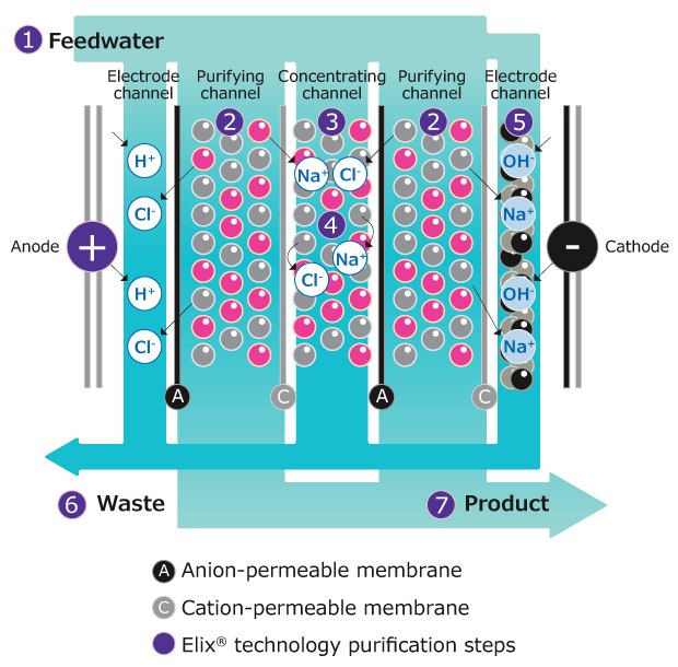
Figure 4.Elix® electrodeionization (EDI) module
Watch a video of how the Elix® EDI module works to efficiently remove ions from pure water.
Electrodeionization benefits & limitations
Benefits
- Effectively removes dissolved inorganics, yielding a resistivity greater than 5 MΩ·cm at 25°C (which corresponds to a total ionic level in water of approximately 50 ppb).
- Greener technology:
- no chemical regeneration
- no chemical disposal
- no resin disposal
- Inexpensive to operate.
Limitations
- Removes only a limited number of charged organics.
- Must be fed by good quality water (for instance, reverse osmosis water) for economically efficient operation.
Ion Exchange
During the ion-exchange process, water percolates through spherical, porous beads (ion-exchange resin). Ions present in the water are exchanged for other ions fixed to the beads. The two most common ion-exchange methods are softening and deionization.
- Softening is primarily used as a pretreatment method to reduce water hardness before other water purification processes, such as reverse osmosis (RO). Softeners contain beads that exchange two sodium ions for every calcium or magnesium ion removed from “softened” water.
- Deionization (DI) involves ion-exchange beads that swap hydrogen ions for cations or hydroxyl ions for anions. These resins are small (< 1.2 mm) and made of polystyrene-based porous material, with ion-exchange binding sites covalently attached to their surface and within the beads. Deionization resins can be packaged in separate bed exchangers for cation and anion exchange, or in mixed bed exchangers that contain both types of resins (see Figure 5). The mixed bed configuration allows for more efficient ion removal and results in higher water resistivity values.
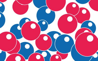
Figure 5.Mixed-bed ion-exchange media
The deionization process in water purification
Deionization is performed as follows (Figure 6):
- Cation-exchange resins are made of polystyrene chains cross-linked by divinylbenzene with covalently bound sulfonic acid groups. These resins exchange a hydrogen ion for any cations they encounter, such as Na+, Ca2+ or Al3+.
- Anion-exchange resins are made of polystyrene polymer chains with covalently bound quaternary ammonium groups. These resins exchange a hydroxyl for any anions (e.g., Cl-, NO3-, SO42-). The hydrogen ion from the cation exchanger unites with the hydroxyl ion of the anion exchanger to form pure water.
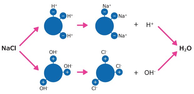
Figure 6.Water deionization process with mixed-bed resins. Example of NaCl in water.
IQnano™ ion-exchange resins are characterized by their small diameter as compared to the Jetpore® ion-exchange resins (Figure 7), and their fast kinetic properties. Combining these two resins allows for a dramatically reduced total media volume, smaller cartridges, and more compact systems, while still achieving ion removal down to trace level.
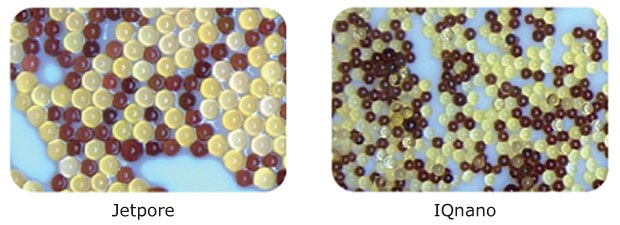
Figure 7.Ion-exchange beads of various sizes used in Milli-Q® water purification systems
Ion-exchange resin regeneration
When a resin’s hydrogen and/or hydroxyl ions have all been exchanged for charged contaminants in the water, a resin becomes saturated. Ion-exchange resins may be regenerated by strong acid and bases. This regeneration reverses the purification process, replacing the contaminants bound to the resins with hydrogen and hydroxyl ions. However, this is a harsh chemical process that may damage the polymer chains constituting the beads, leading to contamination of the resin by organics and particulates, and creating an issue in the production of high purity water.
For the production of high purity water, two solutions exist:
- Use “virgin” mixed bed ion-exchange resin packs containing monospheric beads with low TOC only once and discard the pack after usage. This is an economically acceptable process provided that these packs are fed by pretreated water of good quality to limit the replacement frequency. A good pretreatment should remove not only the bulk of ions to limit the burden of ionic contaminants reaching the resin pack, but also organics, particulates and colloids.
- Regenerate ion-exchange resins with a gentle and continuous procedure such as electrodeionization, to avoid damaging the ion-exchange resin beads and consequently generating contaminants, as in the electrodeionization process (see section above and Figure 4).
Deionization benefits & limitations
Deionization can be an important component of a total water purification system when used in combination with other methods such as RO, filtration and carbon adsorption. DI systems effectively remove ions, but they do not effectively remove most organics and microorganisms. Microorganisms can attach to the resins, providing a culture media for bacteria growth and subsequent pyrogen generation over the long run.
Benefits
- Removes dissolved inorganics (ions) effectively from water, leading to resistivity levels above 18.0 MΩ·cm at 25 °C (corresponding roughly to < 1 ppb total ionic contamination in water).
- Can be regenerated (by acid and bases in “service deionization” or by electrodeionization in water purification systems).
- Relatively low initial capital investment.
Limitations
- Limited capacity: once all ion binding sites are occupied, ions are no longer retained (except when operating in an electrodeionization process).
- Does not effectively remove organics, particles or bacteria.
- Chemically regenerated DI beds can generate organics and particles, and harbor bacteria.
- Single use, “virgin” resins require good quality pretreated water quality to be economically efficient.
Activated Carbon
Activated carbon consists of porous particles that contain a complex network of small pores (Figure 8). One gram of activated carbon has a developed surface of up to 1000 m2. Organic molecules dissolved in water may enter the pores and bind to their walls due to van der Waals forces. The adsorption process is influenced by the diameter of the pores in the activated carbon and by the diffusion rate of organic molecules through the pores. Additionally, the rate of adsorption is a function of molecular weight and the molecular size of the organics.
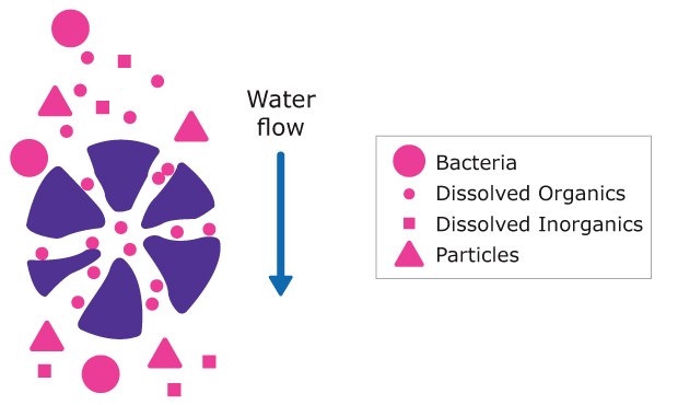
Figure 8.Schematic representation of water purification by activated carbon
Types of activated carbon used in water purification
Activated carbon is usually used in combination with other treatment processes. The placement of carbon in relation to other components is an important consideration in the design of a water purification system.
Activated carbon used in water purification is available in two forms:
- Natural activated carbon produced by treating vegetal products such as coconut shells at high temperature. The result of this process is a fine powder made of irregularly shaped grains. Natural activated carbon contains a high concentration of ionic contaminants and is therefore used only as a pretreatment step to remove excess chlorine from tap water by a reduction reaction and, to some extent, to reduce organic contamination.
- Synthetic activated carbon is made by the controlled pyrolysis of polystyrene spherical beads (Figure 9). This cleaner material is used for the removal of trace organics of low molecular weight from purified water.
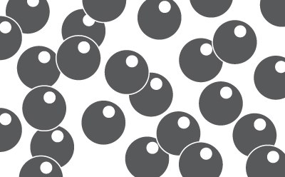
Figure 9.Synthetic activated carbon
Activated carbon benefits & limitations
Benefits
- Effectively removes dissolved organics and chlorine.
- Long life thanks to high binding capacity.
Limitations
- Does not efficiently remove ions and particulates. Can generate carbon fines.
- Limited capacity due to a limited number of binding sites.
Ultraviolet Radiation
Some ultraviolet radiations may be bactericidal, or they may photo oxidize organic contaminants, making UV lamps valuable tools in water purification.
Bactericidal UV radiation
UV radiation has been widely used as a germicidal treatment for water. The adsorption of UV light by the DNA of microbial cells inactivates affected microorganisms.
There are two different types of bactericidal UV lamps (Figure 10):
- Historically, low-pressure mercury lamps emitting light at a wavelength of 254 nm have been used to inactivate microorganisms and prevent bacterial growth and contamination in pure water (Figure 10a).
- Alternatively, patented mercury-free UVC LED emitting at 265 nm (ech2o® bactericidal UV) are increasingly used for high efficiency bacterial inactivation (Figure 10b).

Figure 10.Bactericidal UV lamps: a) low-pressure mercury lamp and b) mercury-free UVC LED.
Bactericidal UV lamps may be located:
- in the water purification system, to control bacteria levels in pure water
- in the reservoir, to maintain low bacterial contamination in the stored pure water and to prevent biofilm development.
Photooxidative UV radiation
The photooxidation of organic compounds dissolved in water ultimately allows their conversion into carbon dioxide. Thanks to photooxidation, Total Oxidizable Carbon (TOC, sometime referred to as ‘total organic carbon’) levels in high purity water can be reduced to 5 ppb or below.
Different types of photo-oxidative UV lamp exist:
- Historically, low-pressure mercury lamps with a very pure quartz sleeve allowing the 185 nm UV wavelength to pass through have been used.
- Alternatively, the ech2o® mercury-free xenon excimer (excited dimer) technology, emitting UV radiations at 172 nm wavelength, ensures the photooxidation of organic contaminants.
Ultraviolet radiation benefits & limitations
Benefits
- Effective sanitizing treatment (bacterial control) and effective oxidation of organic compounds to reach water TOC levels below 5 ppb.
- Efficient and greener alternatives to mercury-containing UV lamps are available.
Limitations
- Photooxidation of organics is a polishing step, able to decrease the TOC level only by a limited amount.
- UV light does not affect ions, particles or colloids.
Microfiltration
Microporous filters can be classified in two categories:
- Depth filters are matted fibers or materials compressed to form a matrix that retains particles by random adsorption or entrapment (Figure 11a).
- Surface filters are made from multiple layers of media. When fluid passes through the filter, particles larger than the spaces within the filter matrix are retained, accumulating primarily on the surface of the filter. Unlike depth filters, they capture particles on the surface of the filter medium. Screen filters (also called membrane filters) are inherently uniform structures which, like a sieve, retain all particles larger than the precisely controlled pore size on their surface (Figure 11b).

Figure 11.Depth (a) and screen (b) filters
Understanding the differences between filter types is essential, as each serves a distinct purpose:
- Depth filters: Commonly used as prefilters, depth filters offer a cost-effective way to remove 98% or more of suspended solids. They protect downstream components from fouling or clogging by trapping contaminants throughout the entire depth of the filter material. For instance, this filter is present in pretreatment cartridges used to protect RO membranes.
- Screen filters: These are the most precise, capturing 100% of particles larger than their pore size. Positioned at the final stage of a water purification system, they eliminate the smallest remaining contaminants—such as resin fragments, carbon fines, colloidal particles and microorganisms. For instance, the Millipak® 0.22 µm final filter effectively retains particles and bacteria at a Milli-Q® system point of dispense.
Microfiltration benefits & limitations
Benefits
- Screen filters are absolute filters that remove all particles and microorganisms greater than their pore size.
- Efficient throughout their lifetime, unless they are damaged.
- Maintenance is limited to replacement.
Limitations
- Do not remove dissolved inorganics, organics or endotoxins.
- Cannot be regenerated.
Ultrafiltration
In contrast with screen (microporous) membrane filters, which remove particles according to pore size, an ultrafiltration (UF) membrane acts like a molecular sieve. UF membranes separate dissolved molecules based on their size. This size is often expressed as molecular weight, though the relationship between size and weight isn't always direct.
In ultrafilters, this separation is achieved by forcing a solution through an extremely fine, selectively permeable membrane (Figure 12). It is a durable, thin membrane that retains most macromolecules larger than a specific threshold, known as the Nominal Molecular Weight Limit (NMWL). This includes colloids, microorganisms, and endotoxins (or pyrogens), and RNases or DNases. Smaller molecules, such as inorganic ions, pass through into the filtrate.
In water purification, ultrafilters are commonly used to produce endotoxin-free, nuclease-free, and protease-free water, which is essential for sensitive applications like cell culture and molecular biology (e.g., Biopak® or SQPAK™ Bio final polishers).
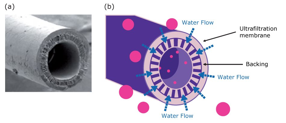
Figure 12.Ultrafiltration hollow fibers: a) scanning electron microscopy (SEM) photo of a UF fiber, b) schematic representation of the ultrafiltration process
Ultrafiltration benefits & limitations
Benefits
- Efficient at removing most particles, pyrogens, enzymes, microorganisms and colloids above their rated size, retaining them on the ultrafilter surface.
- Efficient operation throughout their lifetime, unless they are damaged.
- Their lifetime can be extended by a regular water flush at high speed.
Limitations
- Will not remove dissolved inorganics or organic substances.
- May clog when challenged by an excessive level of high-molecular-weight contaminants.
Support in Selecting a Water Purification System
Contact us if you would like support from a lab water expert in selecting a water system that contains the optimal combination of water purification technologies for your laboratory and its applications.
Related Products
To continue reading please sign in or create an account.
Don't Have An Account?